 Almost a year ago, Inspired LED released the new & improved version of our popular Radiant Edge Series fixtures. Much to the delight of our manufacturing team, the new model was sleeker, brighter, and much easier to build.
Now, we’re passing along the convenience to you!
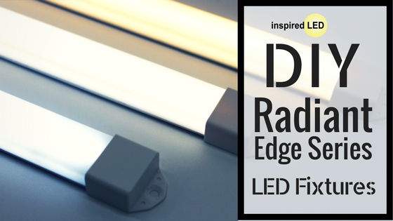
Introducing the new DIY low-profile Radiant Edge System from Inspired LED: a specially designed series of components, including aluminum channels, frosted lenses, end caps, and mounting clips, which allow contractors and customers alike to build their own low-voltage fixtures in field. With just a few simple steps and some basic tools, you can create the perfect lighting solution for any application!
Watch out instructional video here, or follow the steps below to see just how easy it can be…
Materials: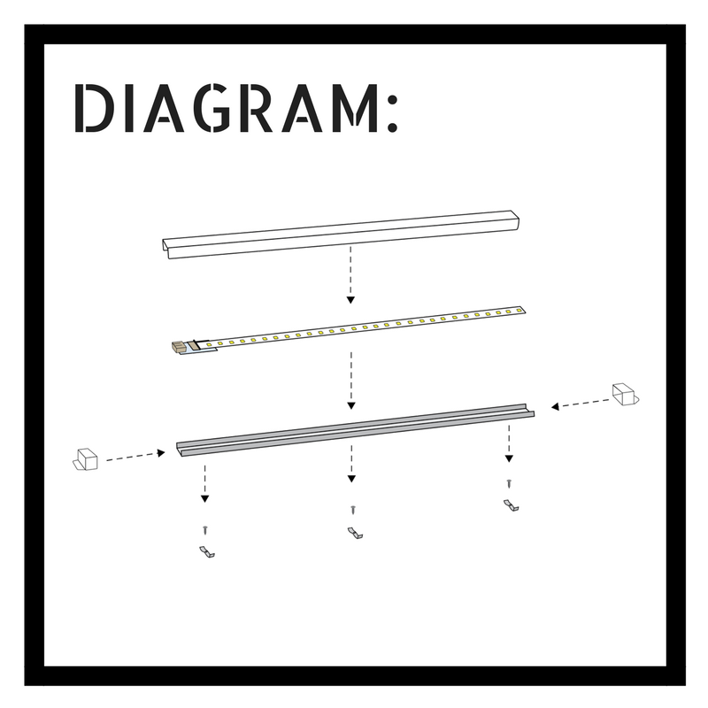
- DIY Short (3/8”) Radiant Edge Lens(es)
- DIY Short Radiant Edge End Caps (some with and some without wiring input holes)
- DIY Radiant Edge Aluminum Channel(s)
- DIY Radiant Edge Mounting Clips (screws included)
- 12V Super, Ultra, or Mega Bright Flexible LED Strips
- Inspired LED’s patented 3.5 x 1.3mm Plug-in Tiger Paw® (to be used with standard interconnect cables)
or Micro-lock Tiger Paw® Connectors (to be used with bulk 16-12AWG solid copper wire) - 12V DC Power Supply or Hardwire Transformer
- Interconnect cables or bulk 16-12AWG solid copper wire (depending on connector style)
- Pair of scissors
- Pair of tin snips or dikes
- Wire strippers (depending on connector style)
- Measuring tape
- Super glue (if desired)
- Phillip’s head screw driver for install
Note: The process of building DIY Radiant Edge panels is fairly simple, however measurements must be made carefully, and instructions followed as precisely as possible to ensure best results. As always, use caution when working with electricity (even low voltage), and if installing a hardwire transformer, we recommend hiring a licensed electrician.
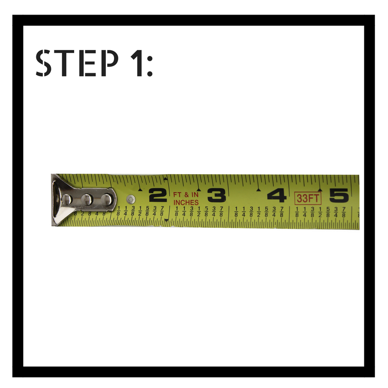
Step 1: To build, begin by measuring the total available space for your completed Radiant Edge panel.
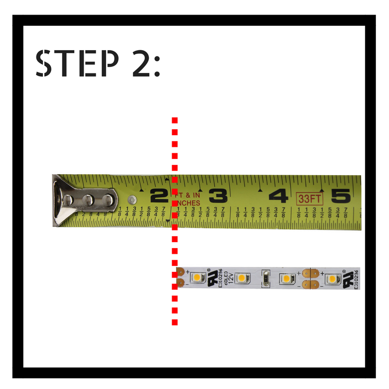
Step 2: Determine the necessary length of your internal LED strip by taking the total available space and subtracting 2” for each connector you will be using. If you’re creating a simple 1-panel system, you will only need a connector on one side, so you will subtract 2” total. If you are creating a “daisy chain” set-up where one panel links to the next, you will need a connector on both sides, so you will subtract 4” total.
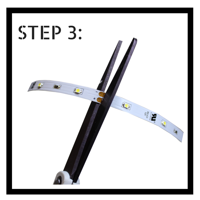
Step 3: Use scissors to cut your flexible LED strip to length. Cut along the copper pads located closest to your final measurement without going over.
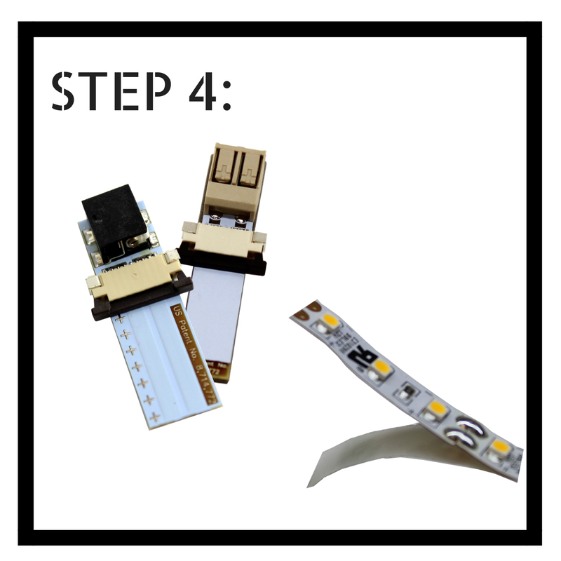
Step 4: Prepare to attach the Plug-in Tiger Paw® or Micro-lock Tiger Paw® by peeling back adhesive the lining from the LED strip (about 1/2″), and pulling open black sliding latch on your connector.
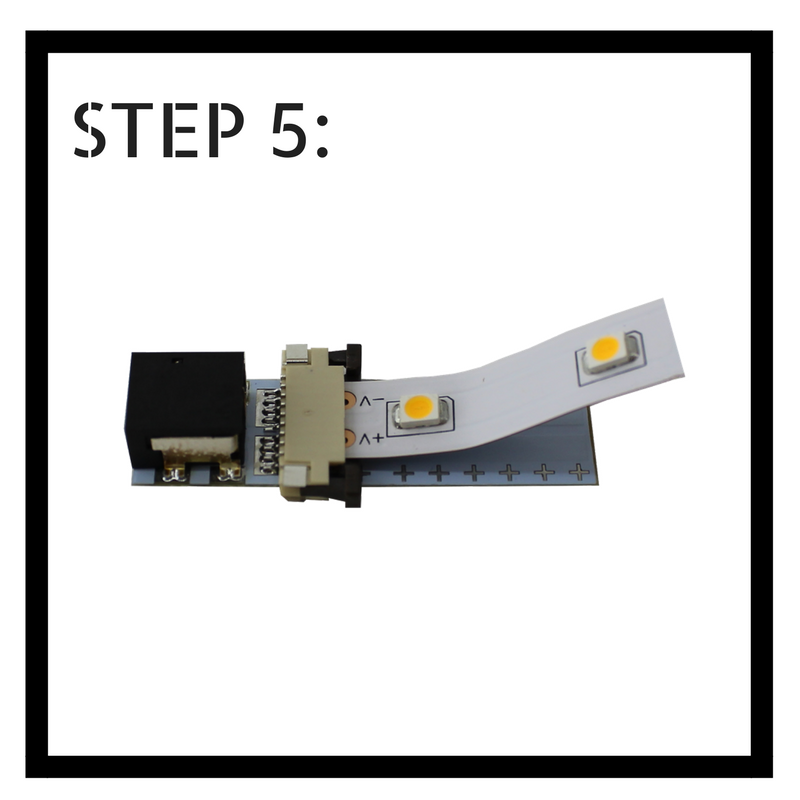
Step 5: Insert the exposed LED strip between the black latch and beige bridge on your connector, then slide latch closed. If you’re using a standard Plug-in Tiger Paw®, ensure (+) polarity of connectors is matched to the (+) polarity as marked along the LED strip.
If using Micro-lock Tiger Paw®, identify the (+) polarity as marked along the strip–this will determine the polarity of wiring in step 10. Your positive wire will align with the positive side of LED flex strip.
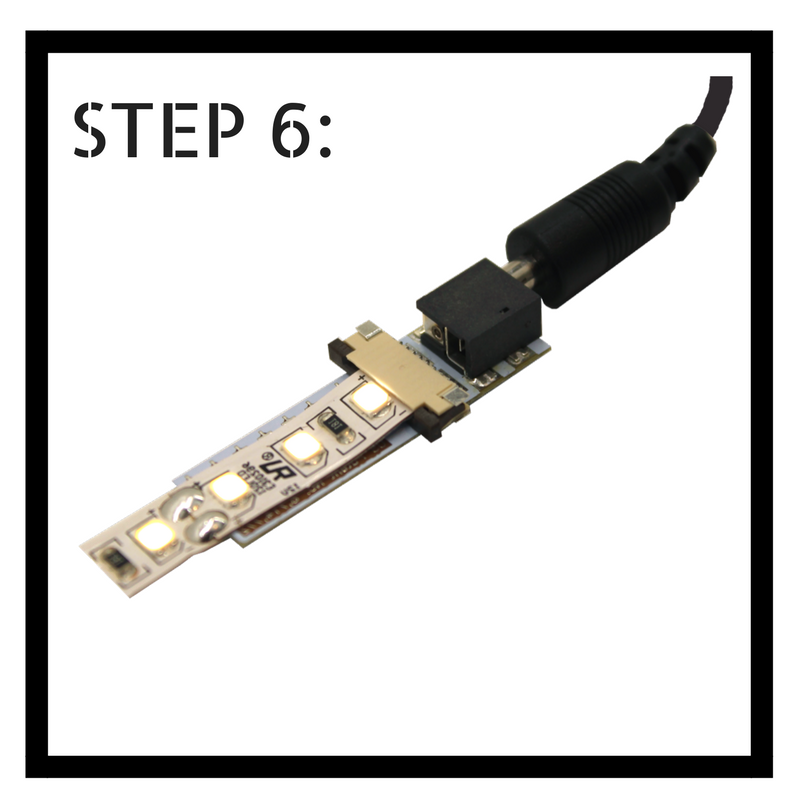
Step 6: Use a 12V DC power supply to test strip functionality. If your LEDsdo not turn on, double check that polarities are properly matched. Repeat steps 4-7 to add connectors to the opposite side of your LED flex as needed.
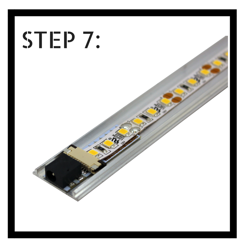
Step 7: Remove the adhesive backing from your finished LED strip and from each of your Tiger Paw® connectors. Carefully align the first connector with the edge of your uncut aluminum channel, and adhere the strip along the center.
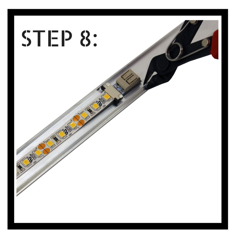
Step 8: Use sharp tin snips or dikes to cut aluminum to length as close as possible to the opposite end of the strip. Snip each raised edge and gently bend aluminum back and forth until it becomes fully separated.

Step 9: Using sharp tin snips or dikes, measure and cut your plastic lens to length. For the easiest cut, first snip each edge then gently bend plastic back and forth until it becomes fully separated.
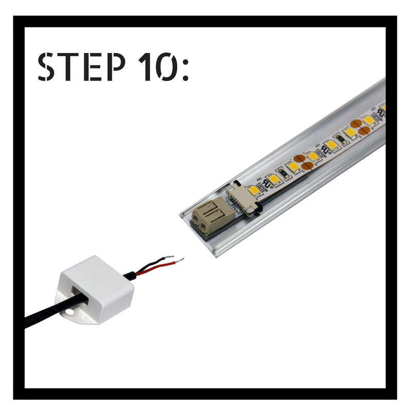
Step 10: If using Micro-lock Tiger Paw® connectors, select your desired 16-22 AWG solid cable and strip back the ends about 1/4” of an inch to expose copper. Then feed wire through end caps (to simplify install later on) match positive and negative polarity to the markings on your LED strip, and insert each wire into the Micro-locks. Check functionality by connecting to power before proceeding.
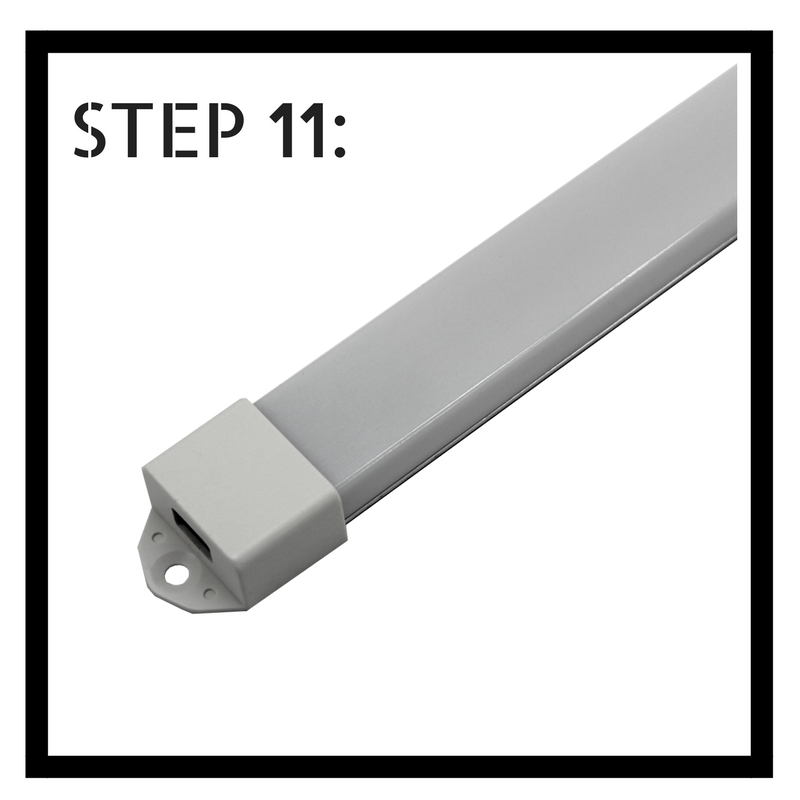
Step 11: If using plug-in Tiger Paws®, or once Micro-lock has been wired up, snap lens onto aluminum and slip desired end caps into place on each side. A dab of super glue may be used to secure caps if desired.
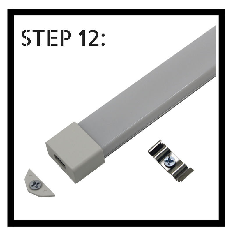
Step 12: To install, you may secure your DIY Radiant Edge panel onto the desired surface using the screw holes located on each end cap. For longer panels, we recommend using mounting clips to provide additional support every 12”. Or, if you prefer, the end cap mounting tabs can be removed entirely by bending firmly back and forth. Panels can then be installed using mounting clips every 12”.
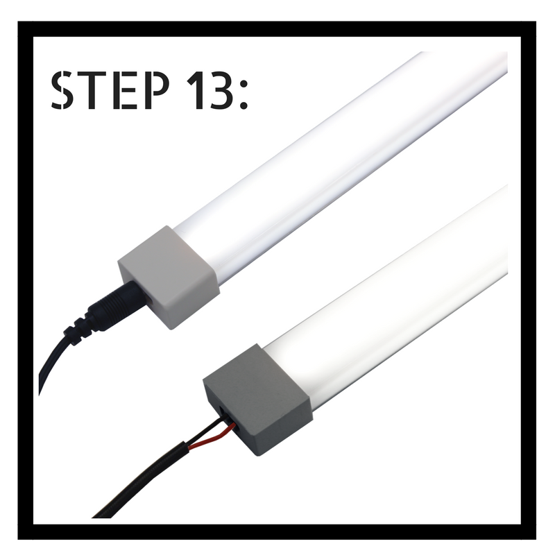
Step 13: If using plug-in Tiger Paws®, use Inspired LED interconnect cables to plug one DIY Radiant Edge panel into the next, ensuring the first panel in series is connected directly to a 12V DC plug-in power supply. If using Micro-lock Tiger Paws®, use bulk wire back to connect from one DIY Radiant Edge panel to the next. Ensure the first panel in series is connected to a 12V DC power supply using wire nuts.
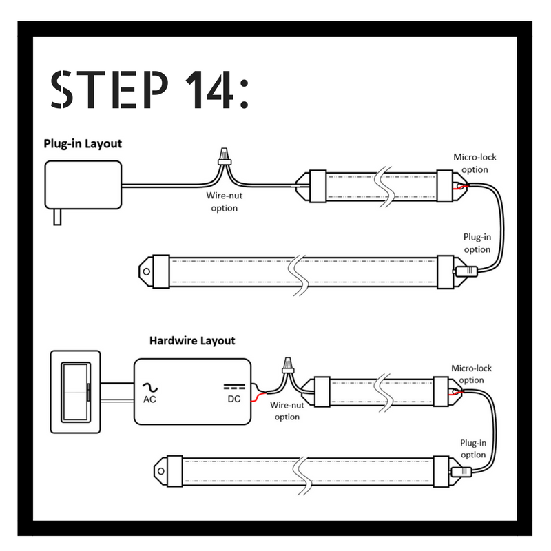
Step 14: Follow corresponding instructions to incorporate switches, dimmers, power supplies and transformers for a complete LED system. Be sure to check the Inspired LED power chart to calculate wattage and voltage drop for the type of LED flex you have selected.
And there you have it! A simple way to create custom LED fixtures with just a bit of creativity and a few basic components. Inspired LED’s DIY Radiant Edge System is the perfect add-on to our Cut & Connect Series Kits, which come with everything you’ll need to build a basic plug & play lighting system- including cables, connectors, power supplies, and flexible LED strips in a variety of brightness levels and color temperatures. Mix and match as needed to create the ideal layout for any home or business!
For more information on Inspired LED products and services, be sure to visit our website: www.inspiredled.com. If you have specific assembly or installation questions about the DIY Radiant Edge system, we are happy to help. Send us an email at orders@inspiredled.com, or give us a call at 480-941-4286.